
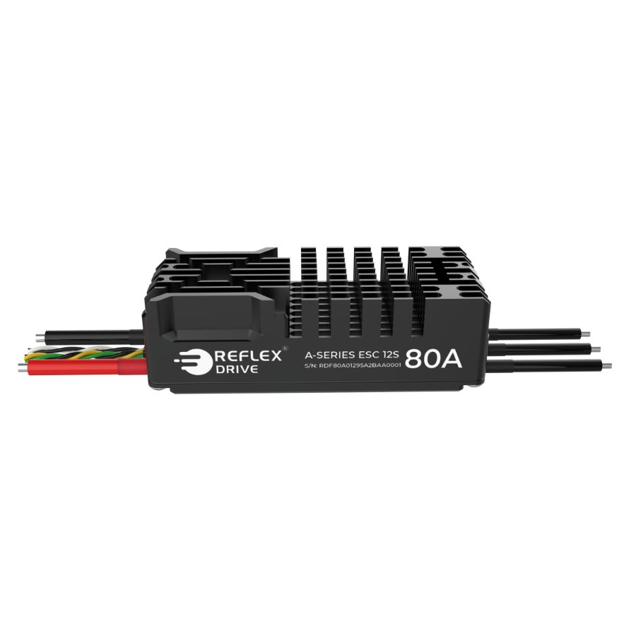
Every ESC is tested with the battery leads it ships with, usually 10 to 15 cm. On a large airframe it is tempting to extend those leads to reach a central battery. Long battery leads add inductance, and that inductance turns the ESC’s fast current switching into voltage spikes on its input. This guide explains what happens, how much capacitance to add when you must extend the leads, where to put it, and what happens at the moment you plug the battery in. Our ESC Lead Capacitance Calculator runs all of these numbers for your own setup.
In short: extend the motor wires instead of the battery leads whenever you can. If the battery leads must be longer, add about 0.93 µF per amp for every extra centimetre (2.35 µF per amp per inch), close to the ESC, and use an anti-spark connector once the added bank reaches thousands of microfarads.
Why battery lead length matters
An ESC switches tens of amps on and off thousands of times a second. The battery leads behave like an inductor, so a fast change in current produces a voltage across them, and the energy stored in that inductance ends up in the ESC’s input capacitors as an overshoot:
v = L · di/dt ΔV ≈ I · √(L / C)
Those spikes heat the input capacitors, stress the MOSFETs and can trip the ESC’s over-voltage protection. The motor wires are different: the motor’s own winding inductance already smooths the current on that side. That is why extending the three motor wires is the preferred fix, and extending the two battery wires is the one that needs care.
A battery lead pair has roughly 4 to 10 nH of loop inductance per centimetre, depending on how close the two wires run. We use 7.9 nH/cm (20 nH/in) for wires taped side by side. A tightly twisted pair is about half that. Long leads also cost voltage and heat:
| Lead length (each wire) | Loop inductance | Resistance, 12 AWG pair | Drop at 55 A | Heat at 55 A |
|---|---|---|---|---|
| 10 cm (4 in) | 79 nH | 1.0 mΩ | 0.06 V | 3 W |
| 30 cm (12 in) | 236 nH | 3.1 mΩ | 0.17 V | 9 W |
| 45 cm (18 in) | 354 nH | 4.7 mΩ | 0.26 V | 14 W |
| 60 cm (24 in) | 472 nH | 6.3 mΩ | 0.34 V | 19 W |
| 90 cm (35 in) | 709 nH | 9.4 mΩ | 0.52 V | 28 W |
| 120 cm (47 in) | 945 nH | 12.5 mΩ | 0.69 V | 38 W |
| 150 cm (59 in) | 1181 nH | 15.6 mΩ | 0.86 V | 47 W |
55 A is the continuous rating of the RD A-Series ESC 80A, which ships with 10 cm, 12 AWG leads. Resistance uses 5.21 mΩ per metre for 12 AWG copper, counted out and back. On long runs, go up a gauge as well as adding capacitance.
How much capacitance to add
The most widely used rule of thumb comes from KDE Direct: add 2.35 µF per amp for each inch of battery lead beyond 12 in (30 cm). KDE’s own example, an 85 A ESC on 36 in leads, works out to 2.35 × 85 × 24 ≈ 4,800 µF. In metric, the same rule is 0.925 µF per amp per centimetre.
We apply the rule from each ESC’s factory lead length rather than from 30 cm, because our ESCs are tested with 10 to 15 cm leads. That gives a somewhat larger, more conservative bank. We also size on the ESC’s peak current rating. Using the continuous rating gives a smaller bank with less margin.
Cadd (µF) = 2.35 × I (A) × (lnew − lfactory) (in)
Worked example: an A-Series ESC 80A with its 10 cm leads extended to 60 cm. The extra length is 50 cm, or 19.7 in, so Cadd = 2.35 × 80 A × 19.7 in ≈ 3,700 µF. That is eight 470 µF capacitors.
Added capacitance in µF for each Reflex Drive ESC, sized on peak current, by total lead length (each wire):
| ESC (factory leads) | Peak current | 30 cm | 45 cm | 60 cm | 90 cm | 120 cm |
|---|---|---|---|---|---|---|
| RD S-Series ESC 25A (10 cm) | 25 A | 463 | 810 | 1,156 | 1,850 | 2,544 |
| RD D-Pro V3 ESC 60A (12 cm) | 60 A | 999 | 1,832 | 2,665 | 4,330 | 5,995 |
| RD A-Series V2 ESC 60A (FOC) (15 cm) | 60 A | 833 | 1,665 | 2,498 | 4,163 | 5,829 |
| RD V-Series ESC 60A 12S (14 cm) | 60 A | 888 | 1,721 | 2,554 | 4,219 | 5,884 |
| RD T-Pro V3 ESC 75A (10 cm) | 75 A | 1,388 | 2,429 | 3,469 | 5,551 | 7,633 |
| RD A-Series ESC 80A (FOC) (10 cm) | 80 A | 1,480 | 2,591 | 3,701 | 5,921 | 8,142 |
| RD V-Series ESC 80A (14 cm) | 80 A | 1,184 | 2,294 | 3,405 | 5,625 | 7,846 |
| RD A-Series ESC 120A (FOC) (10 cm) | 120 A | 2,220 | 3,886 | 5,551 | 8,882 | 12,213 |
| RD Q-Pro V2 ESC 120A (14 cm) | 120 A | 1,776 | 3,442 | 5,107 | 8,438 | 11,769 |
| RD A-Series ESC 150A (FOC) (10 cm) | 150 A | 2,776 | 4,857 | 6,939 | 11,102 | 15,266 |
Why this rule is about the right size: if the extra inductance (≈ 20 nH/in) dumps its energy into the extra capacitance (2.35 µF per amp per inch), the overshoot works out to √(20 nH × I ÷ 2.35 µF), about 0.6 V at 40 A, 0.8 V at 80 A and 1.1 V at 150 A. That is a small fraction of a 12S pack. The overshoot the rule allows grows slowly with current, because the rule scales capacitance with current and not with current squared.
Choosing the capacitors
The rule gives a capacitance. These checks decide which parts to use and how many:
- Voltage rating. At least 1.3 × the full-charge pack voltage, and not below the ESC’s over-voltage limit. For 12S (50.4 V) with A-Series ESCs (OVP 67 to 70 V), use 80 V capacitors. For 6S, 35 V parts are enough.
- Ripple current. With long leads, the battery can no longer supply the ESC’s ripple current, so the capacitors must. Allow for up to about half the continuous current, RMS. At 55 A that is about 27 A. With 2 A rated capacitors you would need 14, more than the 8 the capacitance rule asks for. Ripple rating, not capacitance, often sets the count.
- Low ESR. Heat in each capacitor is ripple current squared times ESR. Use low-ESR electrolytics and several in parallel so they share the current.
- Temperature. Electrolytic life halves for roughly every 10 °C rise. Mount the bank in the airflow and away from the ESC heatsink.
Where to put them
- At the ESC end of the extended lead, within 10 cm (4 in) of the ESC’s own input capacitors. A bank at the battery end does nothing for the lead inductance between it and the ESC.
- Across the + and − wires, with each capacitor’s own legs as short as possible. Long capacitor legs add the inductance you are trying to cancel.
- For leads longer than about 90 cm (3 ft), spread the capacitance along the lead, a group every 20 to 30 cm, with the first group at the ESC.
- Twist or tape the + and − wires together along their whole length. Keeping the pair close roughly halves its inductance.
What happens when you plug the battery in
Connecting a charged battery to an ESC with empty capacitors is a step into a series resistor-inductor-capacitor circuit: the battery’s resistance and inductance, the lead, and the ESC’s input capacitance. Longer leads lower the peak current but reduce damping, so the voltage overshoots further above the pack voltage.
The table models an A-Series ESC 80A on a 12S pack (50.4 V full) with 12 AWG leads. It uses the ESC’s 750 µF of input capacitance, a battery with 25 mΩ and 0.1 µH, and no connector resistance, pre-charge or capacitor ESR. Real connectors and ESR add damping, so treat these figures as upper bounds.
| Lead length | Loop inductance | Damping ζ | Peak inrush | Peak voltage at ESC | Current interruption at 80 A |
|---|---|---|---|---|---|
| 10 cm (factory) | 179 nH | 0.84 | 1,340 A | 50.8 V | 50.4 V |
| 30 cm | 336 nH | 0.66 | 1,124 A | 53.5 V | 50.6 V |
| 60 cm | 572 nH | 0.57 | 938 A | 56.2 V | 50.9 V |
| 100 cm | 887 nH | 0.51 | 789 A | 58.0 V | 51.2 V |
| 150 cm | 1281 nH | 0.49 | 672 A | 59.0 V | 51.4 V |
At 150 cm the plug-in peak reaches 59.0 V, against the ESC’s 67 V over-voltage limit. On a 12S LiHV pack (52.2 V) the same lead peaks near 61 V. ESCs with less input capacitance overshoot further, so check your own model in the calculator. The last column is a sudden stop of the full 80 A, for example when a protection trips: the energy stored in the lead, ½LI², is dumped into the ESC capacitors. It starts from the bus voltage under load, which sits below the pack voltage because of lead and battery resistance, so at 12S the rise mostly recovers that drop. The energy grows with lead length, and on lightly loaded or higher-voltage systems it adds directly to the bus voltage.
What the added bank does to the same plug-in (60 cm leads, 12S, model):
| Case | Capacitance | Damping ζ | Peak inrush | Peak voltage | Energy stored |
|---|---|---|---|---|---|
| ESC only | 750 µF | 0.57 | 938 A | 56.2 V | 1.0 J |
| ESC plus 3,701 µF | 4,451 µF | 1.38 | 1,303 A | 50.4 V (no overshoot) | 5.7 J |
The bank removes the overshoot but raises the plug-in surge by about 39% and stores about 6 times the energy. That surge is what erodes connector contacts and makes the spark. Once the bank is in the thousands of microfarads, use an anti-spark connector (AS150, XT90-S) or a pre-charge resistor:
| Pre-charge resistor | Peak current at 50.4 V | Time to 95%, ESC only (750 µF) | Time to 95%, with bank (4,451 µF) |
|---|---|---|---|
| 5 Ω | 10.1 A | 11 ms | 67 ms |
| 10 Ω | 5.0 A | 22 ms | 134 ms |
| 22 Ω | 2.3 A | 50 ms | 294 ms |
Charge time to 95% is three time constants (3RC). Connect the battery with the throttle at zero, and arm only after the bank is charged.
Checklist
- Measure the battery lead length from the connector to the ESC pads, along one wire.
- Extend the motor wires instead of the battery leads wherever the layout allows.
- Beyond the factory length, add 0.93 µF per amp per extra centimetre (2.35 µF/A/in), sized on peak current.
- Use low-ESR capacitors rated at least 1.3 × pack voltage (80 V for 12S), with enough combined ripple rating.
- Mount the bank within 10 cm of the ESC. Over 90 cm of lead, add a group every 20 to 30 cm.
- Twist or tape the pair, and use heavier wire on long runs.
- Add an anti-spark connector or pre-charge once the bank reaches thousands of microfarads.
- For critical builds, check the ESC input with an oscilloscope at plug-in, full throttle and throttle chop.
The figures in this guide are model estimates, not measurements. Try your own ESC, pack and lead length in the ESC Lead Capacitance Calculator, which shows every step of the calculation.
Talk to our engineers
If you are planning a platform with long battery runs and want help choosing a propulsion setup, email [email protected] or call +91 9151118036. You can also try the Drone Builder to size motors, ESCs and propellers for your aircraft.
